| FileName | Category | Format | Release Date | Operation | |
|---|---|---|---|---|---|
| No documents found. | |||||
| Parameter | Value |
|---|---|
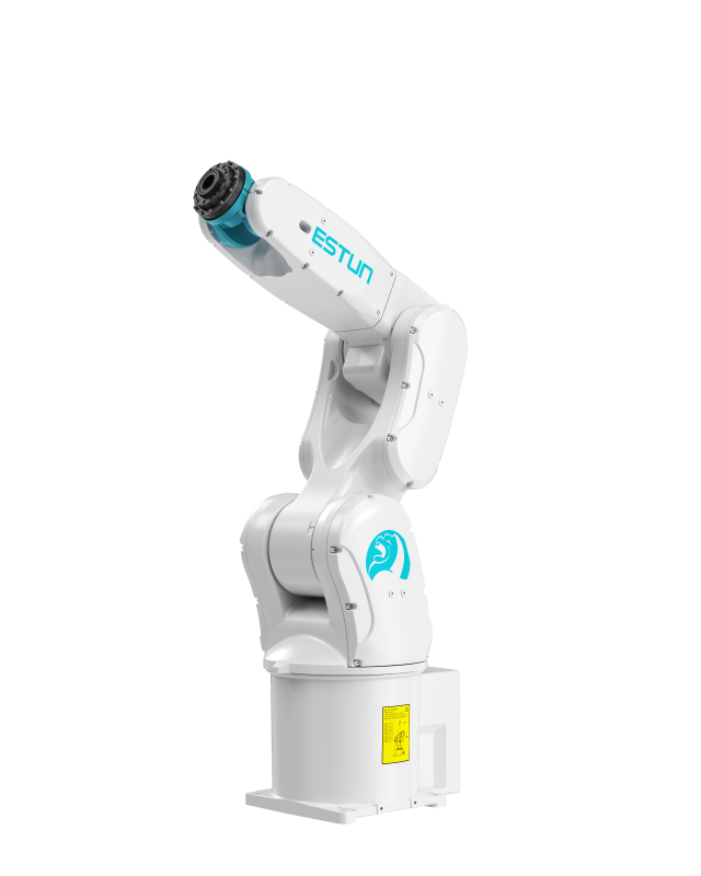
| Model | iER8-720-MI |
| Number of Axes | 6 |
| Maximum Load | 8 kg |
| Maximum Reach | 727 mm |
| Repeat Positioning Accuracy | ±0.02 mm |
| Body Weight | 46 kg |
| Protection Rating | IP67 |
| Mounting Type | Floor/Ceiling |
| Drive Method | AC Servo Motor Drive |
| Installation Conditions | Temperature*: 0 to 45°C Humidity: 20 to 80% RH Allowable Altitude: Below 1000 m Vibration Acceleration: 4.9 m/s² (0.5G) or less No Corrosive Gases Keep away from electrical noise sources. |
| Supported Certification | CE |
*For details, please refer to the manual or consult our company.
| Joint | Motion Range | Maximum Speed | Allowable Load Moment of Inertia / Torque |
|---|---|---|---|
| J1 | -170° ~ +170° | 420°/s | - |
| J2 | -80° ~ +135° | 380°/s | - |
| J3 | -190° ~ +65° | 450°/s | - |
| J4 | -190° ~ +190° | 550°/s | 0.5 kg·m²/17 N·m |
| J5 | -120° ~ +120° | 500°/s | 0.5 kg·m²/17 N·m |
| J6 | -360° ~ +360° | 850°/s | 0.2 kg·m²/10 N·m |
| Installation Parameters | Value |
|---|---|
| Dimensions | 440*330*102 (mm, LWH) |
| Control Cabinet Weight | 10 kg |
| Rated Power | 1.2 kW |
| Reference Energy Consumption | 0.96 kW·h |
| Installation Environment | Ventilated, Non-Sealed |
| Minimum Installation Space | 520*410*182 (mm, LWH) |
| Operating Ambient Temperature | 0°C~45°C |
| Communication Method | Standard: EtherCAT, Modbus TCP, TCP/IP; Optional (requires additional module purchase): Profinet, Profibus, CCLINK, EtherNet IP |
| Interconnect Cable Length (Subject to actual confirmation by the manufacturer's business team) | Standard: 3 m; Optional: 5 m, 5 m (flexible), 10 m, 10 m (flexible), 15 m, 15 m (flexible) |
| Cable Reservation Space to Robot Base | Non-Flexible: ≥450 mm; Flexible: ≥300 mm |
| Power Cable Bending Radius | Non-Flexible: ≥350 mm; Flexible: ≥200 mm |
| Encoder Cable Bending Radius | Non-Flexible: ≥350 mm; Flexible: ≥200 mm |
| I/O Cable Bending Radius | Non-Flexible: ≥350 mm; Flexible: ≥200 mm |
| Heavy-Duty Connector Size to Robot Base | 73*57*72 (mm, LWH) |
| Specification Parameter | Value |
|---|---|
| Control Cabinet Main Power Supply | Single-Phase AC 220V~240V, 50/60Hz |
| Number of Controlled Axes | 3~6 |
| Storage Environment | Temperature: -20°C~60°C; Humidity: 95%RH or below (Non-Condensing, Non-Freezing) |
| Insulation Resistance | 100 MΩ or above |
| Vibration Resistance | 10Hz ≤ f ≤ 57Hz, amplitude 0.15mm |
| Shock Resistance | Maximum not exceeding 15g, duration 11ms |
| Altitude | Below 1000 m |
| EMC Test Standard | IEC 61000-6-2:2019, IEC 61000-6-4:2019 |
| Protection Rating | IP20 |
| Interface Parameter | Value |
|---|---|
| Power Cable Interface | One interface corresponds to 2 axes (3 interfaces for 6 axes; 2 interfaces for 4 axes), used to connect the motor power cables for each robot axis. |
| Heat Dissipation Air Inlet | A filter cotton can be installed inside (optional), used for control cabinet heat dissipation. |
| Mode Selection Switch | Turn left for automatic mode, turn right for manual mode, used to switch the robot control mode. |
| Teach Pendant Interface | Used to connect the cable of the robot teach pendant. |
| LED Indicator Light | System status indication (refer to the indicator light instructions for details), 3 pcs in total. |
| Expansion Slots 1, 2, 3 | Users can select different types of expansion cards according to their needs. |
| Power Switch | Used to control the power on/off of the robot control cabinet. |
| Encoder Interface | Used to connect the motor encoder cables for each robot axis, collect robot position signals and transmit them to the robot body. |
| Ethernet1 Interface | Can connect to an Ethernet slave station, acting as a virtual teach pendant interface. |
| EtherCAT Interface | Can connect to an EtherCAT slave station, used to connect external expansion servo axes or other I/O modules. |
| Ethernet2 Interface | Can connect to an Ethernet slave station. |
| Ethernet3 Interface | Can connect to an Ethernet slave station, and can also connect to the VNC interface. |
| USB Interface | Used for controller data transmission or connecting external devices. |
| Standard I/O Interface | Standard user DI/DO interface for the control cabinet; the system I/O is 6DI, 7DO, and the user I/O is 14DI and 13DO, used for signal connection between external devices and the control cabinet. |
| Safety I/O Interface | Used for connecting safety signals such as external emergency stop and safety doors. |
| Parameter | Value |
|---|---|
| LCD Screen | TFT 7 Inch 800*480 |
| External USB | 2.0*1 |
| Indicator Light | 3 pcs |
| Communication | Ethernet: 1-channel 10/100 Mbps auto-adaptive |
| Accessories | Emergency stop; Key switch; Enable switch (three-position) |
| Operating Environment | Operating Temperature: -10°C ~ 50°C |
| Storage Temperature | -20°C ~ 60°C |
| Teach Pendant Cable Length (Subject to actual confirmation by the manufacturer's business team) | Standard: 8 m; Optional: 15 m, 20 m, 25 m, 30 m |
| Protection Rating | IP54 |
| Weight | 1090±10g (excluding cable) |
| FileName | Category | Format | Release Date | Operation | |
|---|---|---|---|---|---|
| No documents found. | |||||