Front page >Product Center >Industrial Robot >General‑Purpose Robot >SCARA Series
SCARA Series
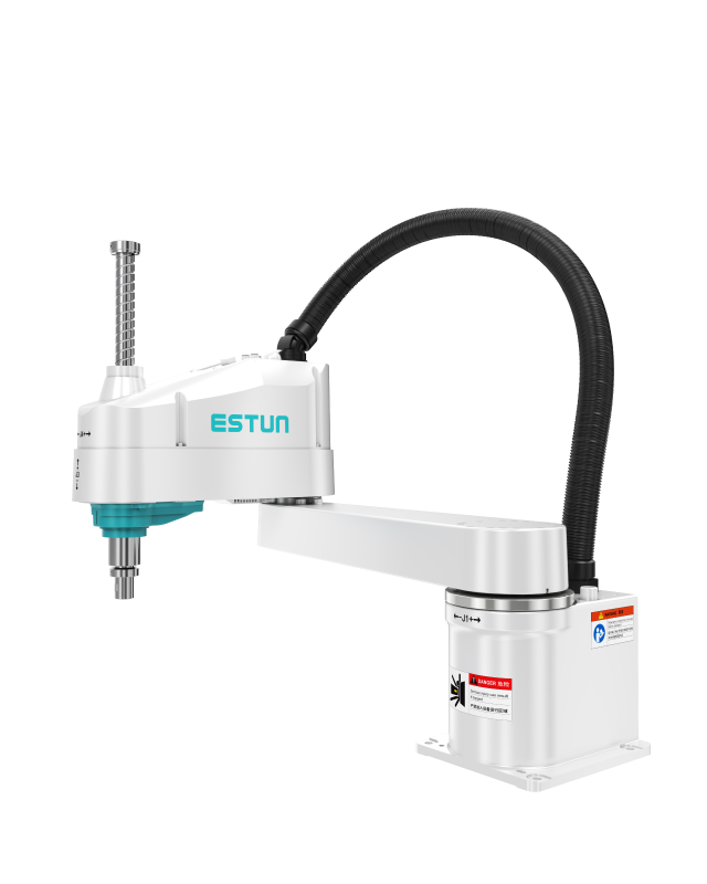
iER10-800-SR
Parameter Parameter Value
Model iER10-800-SR
Number of Axes 4
Maximum Payload 10 kg
Maximum Reach 800 mm
Repeat Positioning Accuracy J1+J2: ±0.02 mm, J3: ±0.01 mm, J4: ±0.01°
Weight of Main Body 25 kg
Protection Rating IP20
Mounting Type Floor
Drive Type AC servo motor drive
Installation Conditions Temperature: 0 to 45°C (no excessive temperature changes); Humidity: 10% to 80% (no condensation); Electrical fast transient/burst immunity: 2 kV or below; Electrostatic immunity: 8 kV or below; Environment: Install indoors, avoid direct sunlight, keep away from dust, oil mist, salt, iron filings, etc.; keep away from flammable and corrosive liquids and gases; do not contact with water; do not transmit impact and vibration, etc.; keep away from electrical interference sources.
Supported Certification CE
*For details, please refer to the manual or consult our company.
Joint Motion Range Maximum Speed Allowable Load Moment of Inertia/Torque
J1 -128°~+128° 360°/s –
J2 -150°~+150° 720°/s –
J3 0~200 mm (optional 300 mm) 1350 mm/s –
J4 -360°~+360° 705°/s Rated 0.02 kg·m², Max. 0.3 kg·m²
  • Combined speed of J1 and J2: 8063 mm/s

 
Installation Parameters Parameter Value
Overall Dimensions 440*330*102 (mm, LWH)
Control Cabinet Weight 9.5 kg
Rated Power 1 kW
Reference Energy Consumption 0.8 kW·h
Installation Environment Ventilated, non-sealed
Minimum Installation Clearance 520*410*182 (mm, LWH)
Operating Ambient Temperature 0°C~45°C
Communication Method Standard: EtherCAT, Modbus TCP, TCP/IP; Optional (modules must be purchased separately): Profinet, Profibus, CCLINK, EtherNet IP
Interconnect Cable Length (subject to actual confirmation by the manufacturer's sales) Standard: 3 m; Optional: 5 m, 5 m (flexible), 10 m, 10 m (flexible), 15 m, 15 m (flexible), 20 m, 20 m (flexible)
Cable Reserved Space to Robot Base Non-flexible: ≥450 mm; Flexible: ≥300 mm
Power Cable Bending Radius Non-flexible: ≥350 mm; Flexible: ≥200 mm
Encoder Cable Bending Radius Non-flexible: ≥350 mm; Flexible: ≥200 mm
IO Cable Bending Radius Non-flexible: ≥350 mm; Flexible: ≥200 mm
Heavy-duty Connector Plug Size to Robot Base -
Specifications Parameter Values
Control Cabinet Main Power Supply Single-phase AC 220V~240V, 50/60 Hz
Number of Controlled Axes 3~6
Storage Environment Temperature: -20°C~60°C; Humidity: 95%RH or below (non-condensing, non-freezing)
Insulation Resistance 100 MΩ or above
Vibration Resistance 10Hz ≤ f ≤ 57Hz, amplitude 0.15 mm
Shock Resistance Max. not exceeding 15 g, duration 11 ms
Altitude Below 1000 m
EMC Test Standards IEC 61000-6-2:2019, IEC 61000-6-4:2019
Protection Rating IP20
Interface Name Parameter Details
Power Cable Interface Motor power cable interface for each robot axis; one interface corresponds to 2 axes (3 interfaces for 6 axes; 2 interfaces for 4 axes)
Cooling Air Inlet Heat dissipation air inlet of the control cabinet; a filter cotton can be installed inside (optional)
Mode Selection Switch Robot control mode key switch: turn left for automatic mode, turn right for manual mode
Teach Pendant Interface Cable interface for the robot teach pendant
LED Indicator Light System status indication (refer to the indicator light instructions for details)
Expansion Slots 1, 2, 3 Users can select and use different types of expansion cards according to requirements
Power Switch Power switch of the robot control cabinet, used to turn on/off the power of the control cabinet
Encoder Interface Motor encoder cable interface for each robot axis, used to collect robot position signals; connected to the robot body using dedicated cables
Ethernet1 Interface Can connect to Ethernet slave stations, used as a virtual teach pendant interface
EtherCAT Interface Can connect to EtherCAT slave stations, used to connect external expansion servo axes or other IO modules
Ethernet2 Interface Can connect to Ethernet slave stations
Ethernet3 Interface Can connect to Ethernet slave stations, connect to VNC interface
USB Interface Used for controller data transmission or connecting peripherals
Standard IO Interface Standard user DI/DO of the control cabinet, used for signal connection between external devices and the control cabinet; system IO is 6DI, 7DO, user IO is 14DI and 13DO
Safety IO Interface Used for connecting safety signals such as external emergency stop and safety door
Parameter Parameter Value
LCD Screen TFT 7-inch 800*480
External USB USB 2.0 x 1
Indicator Lights 3
Communication Ethernet: 1 channel, 10/100 Mbps adaptive
Accessories Emergency stop; Key switch; Enabling switch (3-position)
Operating Ambient Temperature -10°C ~ 50°C
Storage Temperature -20°C ~ 60°C
Teach Pendant Cable Length (subject to actual confirmation by the manufacturer's sales) 8 m, 15 m, 20 m, 25 m, 30 m
Protection Rating IP54
Weight 1090±10 g (excluding cable)
FileName Category Format Release Date Operation
No documents found.