| FileName | Category | Format | Release Date | Operation | |
|---|---|---|---|---|---|
| No documents found. | |||||
| Parameter | Value |
|---|---|
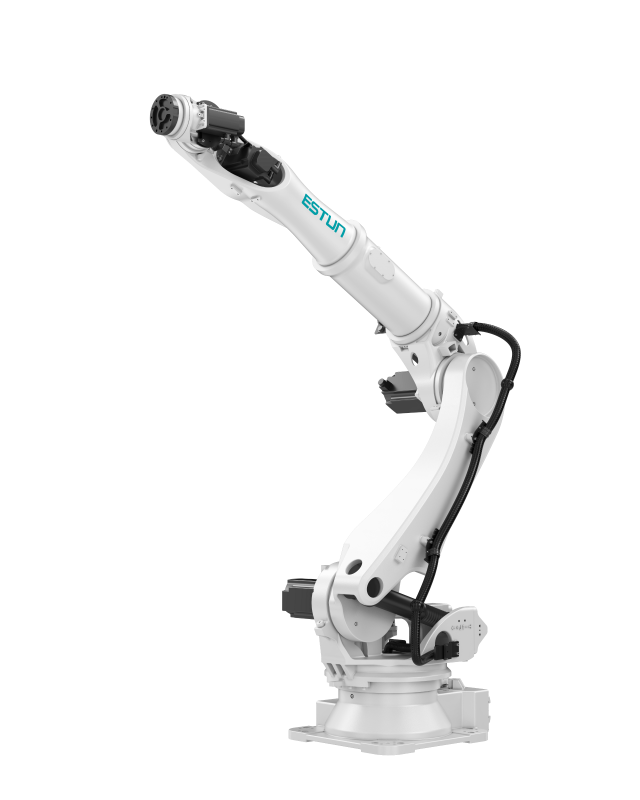
| Model | iER160-3200 |
| Number of Axes | 6 |
| Maximum Load | 160 kg |
| Maximum Reach | 3200 mm |
| Repeat Positioning Accuracy | ±0.06 mm |
| Body Weight | 1150 kg |
| Protection Rating | Wrist IP65, Main Body IP54 |
| Mounting Type | Floor |
| Drive Method | AC Servo Motor Drive |
| Installation Conditions | Temperature: 0 to 45°C; Humidity: 10 to 80% RH; Allowable Altitude: Below 1000 m; Vibration Acceleration: 4.9 m/s² (0.13G) or less; No Corrosive Gases |
| Supported Certification | CE |
| Remarks | For details, please refer to the manual or consult our company |
| Joint | Motion Range | Maximum Speed | Allowable Load Moment of Inertia / Torque |
|---|---|---|---|
| J1 | -180° ~ +180° | 128°/s | - |
| J1 | -180° ~ +180° | 128°/s | - |
| J2 | -60° ~ +80° | 100°/s | - |
| J2 | -60° ~ +80° | 100°/s | - |
| J3 | -95° ~ +80° | 110°/s | - |
| J4 | -250° ~ +250° | 165°/s | 150 kg·m²/1365 N·m |
| J5 | -125° ~ +125° | 150°/s | 150 kg·m²/1365 N·m |
| J6 | -360° ~ +360° | 200°/s | 90 kg·m²/740 N·m |

| Installation Parameters | Value |
|---|---|
| Dimensions | 650*455*750 (mm, LWH) |
| Control Cabinet Weight | 80 kg |
| Rated Power | 7 kW |
| Reference Energy Consumption | 3.64 kW·h |
| Installation Environment | Ventilated, Non-Sealed |
| Minimum Installation Space | 1100*1500*1200 (mm, LWH) |
| Operating Environment | Temperature: 0°C~45°C |
| Communication Method | Standard: EtherCAT, Modbus TCP, TCP/IP, EtherNet IP Optional (requires additional module purchase): EC slave to PN master (HS), EC slave to CC-LINK slave (HS), Modbus to DeviceNET slave (HS), EC slave to Profibus slave (HS) |
| Interconnect Cable Length (Subject to actual confirmation by the manufacturer's business team) | Standard: 8 m Optional: 15 m, 20 m, 10 m (flexible), 15 m (flexible), 20 m (flexible), 25 m (flexible), 30 m (flexible) |
| Cable Reservation Space to Robot Base | Non-Flexible Cable: ≥200 mm Flexible Cable: ≥340 mm |
| Power Cable Bending Radius | Non-Flexible: ≥400 mm Flexible: ≥200 mm |
| Encoder Cable Bending Radius | Non-Flexible: ≥400 mm Flexible: ≥200 mm |
| I/O Cable Bending Radius | Non-Flexible: ≥400 mm Flexible: ≥200 mm |
| Heavy-Duty Connector Size to Robot Base | 120*76*57 (mm, LWH) |
| Specification Parameter | Value |
|---|---|
| Control Cabinet Main Power Supply | Three-Phase AC 380V - 440V, 50/60Hz |
| Number of Controlled Axes | 3~6 |
| Storage Environment | Temperature: -20°C~60°C; Humidity: 95%RH or below (Non-Condensing, Non-Freezing) |
| Insulation Resistance | 100 MΩ or above |
| Vibration Resistance | Complies with GB/T39266-2020-5.2 and IEC 60068-2-6 standards |
| Shock Resistance | Complies with GB/T39266-2020-5.3 and IEC 60068-2-27 standards |
| Altitude | Below 1000 m |
| EMC Test Standard | IEC 61000-6-2:2019 |
| Protection Rating | IP54 |
| Interface Name | Value |
|---|---|
| Teach Pendant Interface | Connection interface between the teach pendant and the control cabinet, used to connect the teach pendant and the control cabinet. |
| I/O Cable Reserved Interface | Reserved I/O cable interface. The metal plate is placed here by default. It can be used for additional I/O cables or SAFETY I/O cables to pass through. For the protection rating of the control cabinet, it is recommended that the hole diameter at the plate be ≤10 mm, and the distance between two holes be greater than 2 times the cable diameter. |
| RJ45 Interface | Used for connection between the external communication network and the control cabinet. The inside of the control cabinet has already been connected to the controller. |
| I/O Cable Reserved Cover Plate | Reserved I/O cable cover plate, convenient for users to route cables from the right side of the control cabinet. It can be used for additional I/O cables or SAFETY I/O cables to pass through. When in use, the metal plate at the reserved I/O cable interface on the back of the control cabinet needs to be removed and moved here. |
| Main Power Cable Inlet | Power inlet of the control cabinet. The power cable needs to pass through this interface into the control cabinet for wiring. |
| Encoder Cable Interface | Straight cable outlet type: The encoder cable passes out of the control cabinet from here. The encoder cable inside the control cabinet is already connected; only connection on the robot side is required. Aviation connector type (optional): The encoder cable is already connected to the aviation connector inside the control cabinet. Users need to secure the encoder interconnect cable to the aviation connector, then connect it on the robot side. |
| Power Cable Interface | Straight cable outlet type: The power cable passes out of the control cabinet from here. The power cable inside the control cabinet is already connected; only connection on the robot side is required. Aviation connector type (optional): The power cable is already connected to the aviation connector inside the control cabinet. Users need to secure the power interconnect cable to the aviation connector, then connect it on the robot side. |
| Air Inlet | Air inlet for the fan inside the control cabinet, used for control cabinet heat dissipation. |
| Air Outlet | Air outlet inside the control cabinet, used for control cabinet heat dissipation. |
| I/O Cable Interface | Straight cable outlet type: The I/O cable passes out of the control cabinet from here. The I/O cable inside the control cabinet is already connected; only connection on the robot side is required. Aviation connector type (optional): The I/O cable is already connected to the aviation connector inside the control cabinet. Users need to secure the I/O interconnect cable to the aviation connector, then connect it on the robot side. |
| Parameter | Value |
|---|---|
| LCD Screen | TFT 7 Inch 800*480 |
| External USB | 2.0*1 |
| Indicator Light | 3 pcs |
| Communication | Ethernet: 1-channel 10/100 Mbps auto-adaptive |
| Accessories | Emergency stop; Key switch (two-position); Enable switch (three-position) |
| Operating Environment | Operating Temperature: -10°C~50°C |
| Storage Temperature | -20°C~60°C |
| Teach Pendant Cable Length (Subject to actual confirmation by the manufacturer's business team) | Standard: 8 m; Optional: 15 m, 20 m, 25 m, 30 m |
| Protection Rating | IP54 |
| Weight | 1090±10g (excluding cable) |
| FileName | Category | Format | Release Date | Operation | |
|---|---|---|---|---|---|
| No documents found. | |||||