| FileName | Category | Format | Release Date | Operation | |
|---|---|---|---|---|---|
| No documents found. | |||||
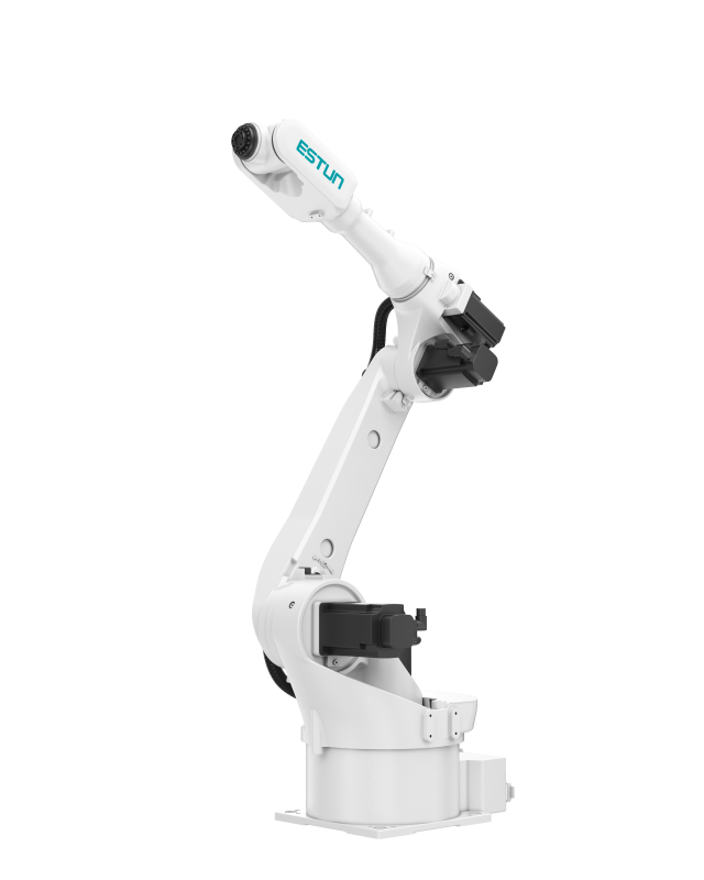
| Parameter | Value |
|---|---|
| Model | iER20-1760 |
| Number of Axes | 6 |
| Maximum Load | 20 kg |
| Maximum Reach | 1756 mm |
| Repeat Positioning Accuracy | ±0.03 mm |
| Body Weight | 273 kg |
| Protection Rating | Wrist IP65, Main Body IP54 |
| Mounting Type | Floor/Ceiling |
| Drive Method | AC Servo Motor Drive |
| Installation Conditions | Temperature: 0 to 45°C; Humidity: 20 to 80% RH; Allowable Altitude: Below 1000 m; Vibration Acceleration: 4.9 m/s² (0.5G) or less; No Corrosive Gases |
| Supported Certification | CE |
*For details, please refer to the manual or consult our company.
| Joint | Motion Range | Maximum Speed | Allowable Load Moment of Inertia / Torque |
|---|---|---|---|
| J1 | -170° ~ +170° | 206°/s | - |
| J2 | -100° ~ +155° | 206°/s | - |
| J3 | -160° ~ +86° | 238°/s | - |
| J4 | -200° ~ +200° | 480°/s | 1.30 kg·m²/47.6 N·m |
| J5 | -135° ~ +135° | 412°/s | 1.30 kg·m²/47.6 N·m |
| J6 | -360° ~ +360° | 705°/s | 0.35 kg·m²/21.4 N·m |
| Installation Parameters | Value |
|---|---|
| Dimensions | 620*550*750 (mm, LWH) |
| Control Cabinet Weight | 130 kg |
| Rated Power | 3 kW |
| Reference Energy Consumption | 2.74 kW·h |
| Installation Environment | Ventilated, Non-Sealed |
| Minimum Installation Space | 1000*1600*1200 (mm, LWH) |
| Operating Environment | Temperature: 0°C~45°C; Humidity: 20%~80% RH |
| Communication Method | Standard: EtherCAT, Modbus TCP, TCP/IP, EtherNet IP; Optional (requires additional module purchase): EC slave to PN master (HS), EC slave to EC master (SD), EC slave to PN slave (ET), EC slave to CC-LINK slave (HS), Modbus to DeviceNET slave (HS), EC slave to Profibus slave (HS) |
| Interconnect Cable Length (Subject to actual confirmation by the manufacturer's business team) | Standard: 7 m; Optional: 3 m, 8 m, 10 m (flexible), 15 m, 15 m (flexible), 20 m, 20 m (flexible), 25 m (flexible), 30 m (flexible) |
| Cable Reservation Space to Robot Base | Non-Flexible Cable: ≥800 mm; Flexible Cable: ≥300 mm |
| Power Cable Bending Radius | Non-Flexible: ≥690 mm; Flexible: ≥200 mm |
| Encoder Cable Bending Radius | Non-Flexible: ≥400 mm; Flexible: ≥200 mm |
| I/O Cable Bending Radius | Non-Flexible: ≥260 mm; Flexible: ≥130 mm |
| Heavy-Duty Connector Size to Robot Base | 120*45*75.5 (mm, LWH) |
| Specification Parameter | Value |
|---|---|
| Control Cabinet Main Power Supply | Three-Phase AC 380V, -15% ~ +10%, 50/60Hz |
| Number of Controlled Axes | 4 ~ 6 |
| Storage Environment | Temperature: -25°C ~ 55°C; Humidity: 95%RH or below (Non-Condensing, Non-Freezing) |
| Insulation Resistance | 100 MΩ or above |
| Vibration Resistance | 4.9 m/s² |
| Shock Resistance | 19.6 m/s² |
| Altitude | Below 1000 m |
| EMC Test Standard | IEC 61800-3:2017 |
| Protection Rating | IP54 |
| Interface Parameter | Value |
|---|---|
| Teach Pendant Interface | Used to connect the teach pendant and the control cabinet. |
| Main Power Cable Interface | Power inlet of the control cabinet. The power cable needs to pass through this interface into the control cabinet for wiring. |
| Grounding Stud | Used for grounding, connected to the body base. |
| I/O Cable Interface | The I/O cable inside the control cabinet passes out from here. |
| 6-Axis Encoder Cable Interface | The robot's encoder cable passes out of the control cabinet from here. The encoder cable inside the control cabinet is already connected; only connection on the robot side is required. |
| I/O Cable Reserved Interface | Reserved I/O cable interface, can be used for additional I/O cables or SAFETY I/O cables to pass through. |
| Remote Operation Elf Antenna Reserved Interface | Reserved interface, used for routing the optional remote operation elf antenna out of the cabinet. |
| Reserved Interface | Reserved cable outlet position, currently sealed with a metal plate. Users can modify the metal plate according to their needs to route cables out, but the IP rating must be guaranteed. |
| 6-Axis Power Cable Interface | The robot's power cable passes out of the control cabinet from here. The power cable inside the control cabinet is already connected; only connection on the robot side is required. |
| Parameter | Value |
|---|---|
| LCD Screen | TFT 7 Inch 800*480 |
| External USB | 2.0*1 |
| Indicator Light | 3 pcs |
| Communication | Ethernet: 1-channel 10/100 Mbps auto-adaptive |
| Accessories | Emergency stop; Key switch; Enable switch (three-position) |
| Operating Environment | Operating Temperature: 0°C ~ 45°C |
| Storage Temperature | -20°C ~ 70°C |
| Teach Pendant Cable Length (Subject to actual confirmation by the manufacturer's business team) | Standard: 8 m; Optional: 15 m, 20 m, 25 m, 30 m |
| Protection Rating | IP54 |
| Weight | 1090±10g (excluding cable) |
| FileName | Category | Format | Release Date | Operation | |
|---|---|---|---|---|---|
| No documents found. | |||||